Physical principles of ESWT
Basic physical principles
Download the following text as pdf-file »
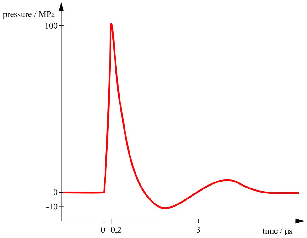
From the physical point of view a shock wave is defined by an abrupt, nearly discontinuous change in pressure and by having a velocity that is higher than the speed of sound in the medium it propagates [1]. A typical pressure profile of a focused shockwave used for therapeutic purposes is shown in fig. 1. Generally a shock wave can be described as a single pulse with a wide frequency range (from approx. 150 kHz up to 100 MHz), high pressure amplitude (up to 150 MPa), low tensile wave (up to -25 MPa), small pulse width and a short rise time of up to a few hundred nanoseconds.
There are three different shockwave generator technologies used today.
The first uses the electrohydraulic principle (fig. 2a). An electrode is placed in the first focal point F1 of a water-filled semi-ellipsoid reflector and high voltage is applied to the tips of the electrode. Thereby, an electric spark is generated between these tips and a spherical shock wave is released by the rapid vaporization of the water between the tips. The shockwave spreads out from the applicator leading to a low intensity radial primary wave, followed by a focused shockwave with focus F2 which occurs due to the reflection of the spherical wave at the reflector.
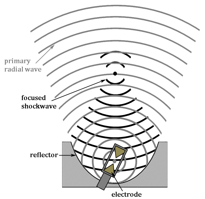
Fig. 2a: Electrohydraulic shockwave transducer.
The second generator is the electromagnetic one, which uses an electromagnetic coil and a metal membrane opposite to it. A low-pressure acoustic pulse is generated by acceleration of the membrane away from the coil due to electromagnetic forces. There are two construction types of electromagnetic shockwave generators. The first one creates a plane wave, which is focused by an acoustic lens. The focal point is defined by the focal length of the lens. The second construction type uses a cylindrical source which creates a cylinder shaped pressure wave. In this case focusing is achieved by reflection of the wave at a hyperbole shaped metal reflector. The two principles of electromagnetic shockwave generators are shown in fig. 2b.

Fig. 2b: Electromagnetic shockwave transducer (© STORZ MEDICAL AG, Trägerwilen, Switzerland).
The third generator forms acoustic waves using the piezoelectric effect, which is the ability of some materials to deform when voltage is applied. A few hundred piezoelectric crystals are mounted on a spherical surface. When a high voltage pulse is applied to the crystals they immediately expand generating a low pressure pulse in the surrounding water. To increase the pulse energy some piezoelectric shockwave sources consist of a double layer of piezo elements. In contrast to the other technologies the piezoelectric system is self-focusing by the geometric shape of the sphere and no focusing lenses or reflectors are needed. The principle is shown in fig. 2c.
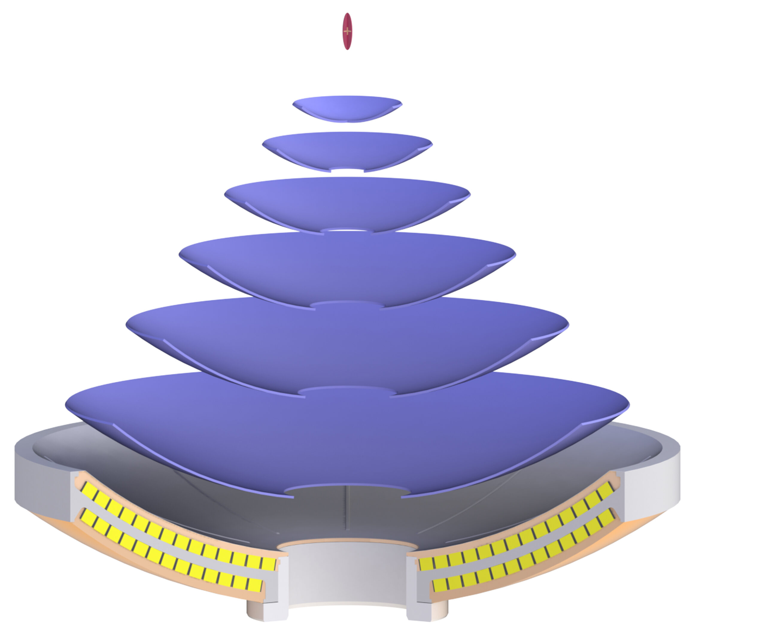
Fig. 2c: Piezoelectric shockwave transducer (© Richard Wolf GmbH, Knittlingen, Germany).
While the electrohydraulic generator produces a shockwave during the explosion between the electrodes, electromagnetic and piezoelectric sources produce an “ordinary” sound wave. The shockwave is formed on the way towards the focal point due to nonlinear effects of sound propagation in water. Those nonlinear effects lead to the steepening of the wave (= shortening of the rise times) as well as an increase of the maximum pressure, because higher pressures move faster than low pressures.
In contrast to focused shockwaves generators, which can produce shockwaves at least at the focal point, radial “shockwave” generators produce “ordinary” sound waves [2] with pressures of up to 30 MPa and much higher rise times of about 3 µs (fig. 3).
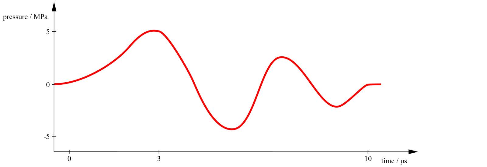
Fig. 3: Schematic pressure profile of a radial “shockwave”.
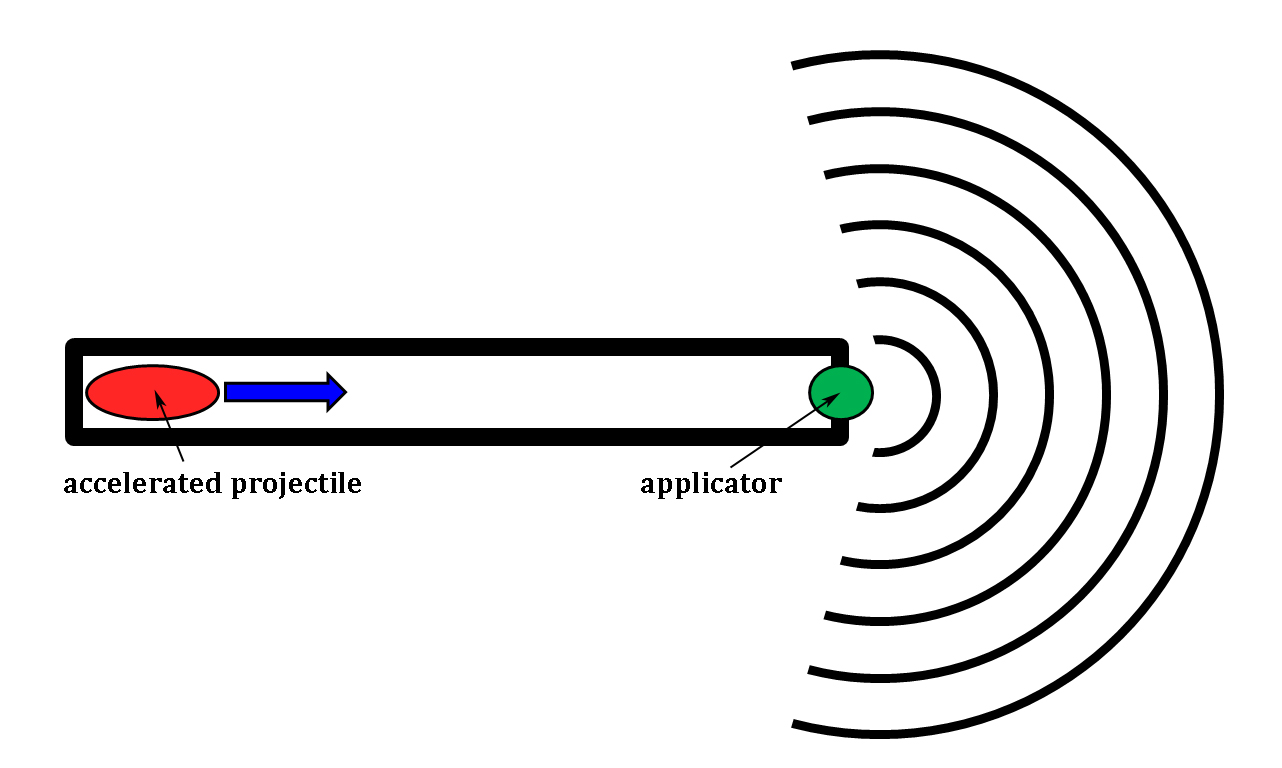
There are currently two different technologies producing radial “shockwaves”. Both use the ballistic principle and consist of a handpiece with a projectile which is accelerated towards an applicator. Upon impact, a wave is produced which propagates in radial direction from the applicator, which is why the highest energy and pressures are located directly at the applicators surface. The difference between the two radial technologies is the acceleration process of the projectile which can either be accomplished by applying air pressure to the projectile (pneumatic principle) or by electromagnetic acceleration. The principle of radial shockwave generation is shown in fig. 4.
As any other wave, the shockwave is subject to the physical laws of reflection, refraction, diffraction and absorption. Therefore the amplitude of the wave and the sound field shape can be changed by interaction with different tissue layers inside the patients’ body or the setup used for in-vitro experiments [3]. Especially reflection at air causes disturbing influences. As 99% of the wave is reflected at any air bubble, the shockwave transducer has to be coupled for example with ultrasound gel to the patients’ body. If the coupling is disturbed by bubbles, the energy reaching the patient’s body is decreased significantly and the therapeutic effectiveness is reduced [4]. Additionally the mechanical strain on tissue at air interfaces is increased, as the reflected wave is reversed (positive pressures become negative and vice versa). Therefore any shockwave therapy of tissue in the vicinity of air interfaces as the lung or intestines can lead to the rupture of those tissues and therefore possible serious side effects.
For focused shockwaves the shockwave parameters as the energy density, maximum and minimum pressure and spatial expansion of the focus are defined in standard IEC61846 [5]. Nowadays they are usually measured with a fiber optic probe hydrophone using an approx. 100µm diameter glass fiber. With this the pressure-time curves of the shockwave can be measured at each position in the 3-dimensional sound field in a water tank.
Due to the aforementioned physical effects by tissue interfaces, the shockwave inside the patient will most likely be changed significantly. Therefore the shockwave parameters describing the shockwave characteristics will be invalid at the location of the treated tissue inside the patient as well as in-vitro.
[1] http://physics.info/shock/
[2] Ueberle, F.; Rad, A. J.; “Ballistic Pain Therapy Devices: Measurement of Pressure Pulse Parameters”; Biomed Tech, 2012; 57 (Suppl. 1), 700-703
[3] Dietz-Laursonn, K.; Beckmann, R.; Ginter, S.; Radermacher, K. & de la Fuente, M.; “In-vitro cell treatment with focused shockwaves – influence of the experimental setup on the sound field and biological reaction”; Journal of Therapeutic Ultrasound, 2016; 4, 2-14;
[4] Pishchalnikov, Y. A.; Neucks, J. S.; VonDerHaar, R. J.; Pishchalnikova, I. V.; Jr., J. C. W. & McAteer, J. A.; “Air Pockets Trapped during Routine Coupling in Dry Head Lithotripsy Can Significantly Reduce the Delivery of Shock Wave Energy”; Journal of Urology, 2006; 176(6Pt1), 2706-2710
[5] IEC 61846: 1998-04, “Ultrasonics – Pressure pulse lithotripters – Characteristics of fields”
Contact us
Call Us
+43 (650) 2332059
Email Us
shockwave@ismst.com
Our Location
Ebelsberger Schlossweg 5
A-4030 Linz / Austria